New Waveform 3D Roughing Machining Strategy

This new roughing strategy is a high speed machining technique that maintains a constant tool cutting load by ensuring the tool engagement into the material is consistent. The tool path moves in a smooth path to avoid sharp changes in direction which maintains the machine tool’s velocity and can dramatically decrease the machining cycle time.

This strategy is superior to the traditional Roughing cycle where machinable geometry features are offset (inward or outward) by a stepover. Traditional tool paths have to run slower feeds and speeds due to the variable width of cut conditions encountered in corners. Tool load spikes as chip thickness increases in areas where the tool finds more material than it did while cutting in a straight line.
 

New Feature Extraction Options

  • New “Open Air Pocket” Feature Extraction method
  • When using this new Feature Extraction method, the contour finder will attempt to return pocketed areas and outline geometries rather than purely closed contours. In addition, for open areas which extend across the entire part, the ends of those closed geometries are automatically set as open elements, allowing them to be machined correctly.
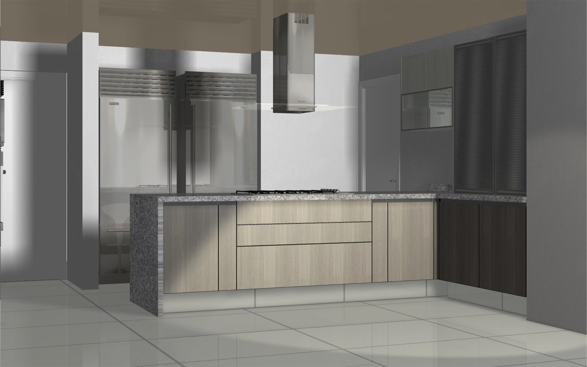
  • This is quite beneficial for parts such as a simple cabinet side, as shown in the image to the right.
  • Improved part alignment control
  • The default X and Y datum (reference) point can now be configured for automatic solid part alignment. The default Z-level zero point can now also be set to the middle of the part. In addition, the Align Part command now supports selection of multiple solids.
  • New options to automatically run a Geometry Query after feature extraction.
 

New Automatic Rapid Manager

This new feature utilizes a new Global Safe Rapid Level property in conjunction with the Machine Configuration settings to help safely manage the rapid positioning moves between work planes and other multiple axis operations.

In addition, rapid positioning moves have been improved on all multiple axis operations so that the tool stays normal to the start/end points during approach and retract.
These enhancements can dramatically improve the simulation results on multiple axis parts.
 

Additional Operation Associativity and Editability Improvements

  • 3D Project and/or Slow Down For Corners can now be easily applied and/or edited directly from the operation’s menu in the Project Manager.

    In addition, these settings are now associated and maintained within the operation. So when an operation is edited/updated, these settings are automatically reapplied.
     
  • Special Edits Manager - If special edits, such as Tool Axis Conversion, 3D Project, or Slow Down For Corners, have been applied to an operation, this new command becomes available and can be used to set the sequence in which these edits should be (re)applied when the operation is edited or updated. The order that these edits are applied can greatly impact the resulting tool path.
     
  • Improved feedback and support for manually edited tool paths - When manually editing a tool path (e.g., via most commands within Machine ►Edit Machining) the user is now informed if the intended edit will prevent future editing or updating of the operation.

    In addition, there is now a new Discard Tool Path Edits command that removes any previously applied manual edits (e.g., Support Tags) and returns the operation to an editable state.
 

3D Polyline Boundaries

Closed 3D polylines can now be used as boundaries for 3D machining operations without having to first convert them to 2D geometries, saving several steps and valuable time.


New Add-Ins

  • Blum Exchange Format (BXF) Translator - This new add-in provides the ability to read BXF files exported from Blum's Dynaplan software and convert them to ALPHACAM drawings.

    There is also an option to automatically send the converted files (ALPHACAM drawings) to the CAD to CAM Style-Layer Processing parts list ready for processing.
     
  • AutoQueries - This new add-in provides the ability to apply multiple Geometry Queries at one time.
     
  • Geometry Z Levels from Parallel Planes - This new add-in provides the ability to convert identical (duplicate) geometries residing on parallel work planes to a single geometry with top/bottom Z levels applied (for Auto Z machining), removing them from their work planes.

    This command is particularly useful for imported CAD (e.g., DXF) file geometries which contain a “thickness”, having one geometry that represents the “top” and another that represents the “bottom”.
     
  • Input CAD Extensions - This new add-in provides the following additional (special) geometry manipulation options when importing DXF/DWG files…
    • Create Geometry Z Levels from Parallel Planes
    • Convert Splines to Lines/Arcs
    • Run Geometry Query or AutoQuery


Part Modeler Enhancements

  • New optional CAD loader that allows Autodesk Inventor parts and assemblies to be loaded into Part Modeler.
     
  • The Creo Parametric loader has been updated to support Creo Parametric version 2.0 models.
     
  • The new 3D Construction menu ► Operation ► Remove Face command allows you to remove features from a 3rd party solid model (a model with no history of features in the tree browser).
     
  • Enhanced Surface Finish Attributes dialog.
    • The Surface Attribute Viewer has been integrated into the dialog; move between tabs for visual feedback of face settings
    • New Formed Size setting (Surface Finish drop-down list) denotes the face is already to size and requires no machining (i.e. a cast/forged finish or previously machined face – no stock to remove)
    • Use the Machined Faces Viewer to see which faces are ‘to size’ and which require machining
    • Surface Attribute colors are only displayed when dialog is active to ensure surface finish colors do not overwrite user defined colors
       
  • Rendered image on tapped holes
     
  • Enhanced editing procedures editing a procedure by double-clicking the feature on the model
 

General Enhancements

  • Many CLS licensing enhancements, including multiple Servercode support
  • Default Coolant value can now be set within tool definition
  • Auto 3D leads for Machine Surface with Tool Side
  • Auto 3D leads for Cut Between 2 Geometries
  • Can now 3D project geometries, polylines or splines to STL parts
  • Multiple tool notes can now be applied to Operations and saved within Machining Styles
  • New Feedrate Modifier (%) for lead-in/out moves
  • Take Account Previous Machining now supports existing saw paths
  • New Tool Offset from Center Line option in Cylindrical Parallel machining strategy
  • Many API enhancements